


For Weintek products
05.12.2025
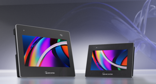
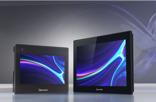
Human Machine Interface
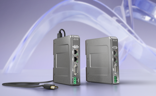
PLC and Remote IO
Accessories

For Weintek products
05.12.2025
Author
Source: www.weintekusa.com
Why support for Modbus TCP matters
Modbus is one of the original open industrial protocols and remains a smart choice for automation projects. Its widespread use across countless devices makes it ideal when vendor-specific communication isn’t an option. With a simple architecture and easy-to-understand packet structure, even those new to Modbus can quickly integrate it into their products.
And when a device doesn’t natively support Modbus, low-cost bridge or gateway devices can convert proprietary or uncommon protocols into Modbus, making integration with a wide range of devices quick and hassle-free.
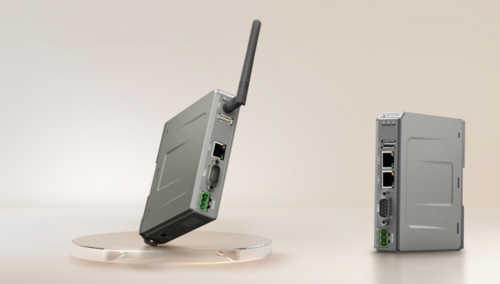
What Makes Weintek’s CODESYS Unique
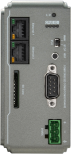
While many know Weintek as a leading HMI provider, few realize that our products also include an optional CODESYS soft PLC, creating a powerful, low-cost HMI + PLC solution. What makes Weintek’s CODESYS implementation unique is its architecture: the HMI and PLC do not compete for hardware resources. The built-in CODESYS PLC is allocated a dedicated CPU core, Ethernet port, and, on applicable units, a CAN bus port. This dedicated hardware ensures the CODESYS runtime operates independently, preventing the HMI application from consuming resources reserved for the RTOS.
This separation extends to programming as well. HMI visualization is developed using EasyBuilder Pro, Weintek’s intuitive HMI programming software, which supports over 400 industrial protocols. The CODESYS runtime, meanwhile, is programmed using the standard CODESYS IDE, available on the Weintek USA forum or Weintek website.
Beyond performance and programming flexibility, CODESYS opens the door to additional protocols and integration options. For example, Weintek offers a variety of EtherNet/IP drivers which include generic drivers compatible with many devices. However, CODESYS provides native EtherNet/IP support and a simple EDS import process for developers. For a full list of supported protocols in Weintek’s CODESYS, please refer to the CODESYS data sheet.
Step-by-Step Setup: CODESYS Modbus TCP integration
Unlike the use of EtherNet/IP, Modbus TCP does not require you to update the the firmware of your device. However, you will need to install our Codesys package and an instance of the Codesys IDE.
Codesys Installation
We highly recommend using Codesys 3.5.15.50 as the recommended Modbus TCP driver was validated within this version. To install Codesys, please see the section labeled “Where can I download Codesys?” in this post.
Codesys Project
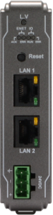
Step 1: Connect your PC to the HMI as shown within this tutorial: Link
Note: The location of the “CODESYS login” function may vary by device type and firmware. The three possible locations of this option are shown below.
A. The “CODESYS login” option may reside within the “Network” settings menu.

B. The “CODESYS login” option may reside within the “CODESYS” settings menu under the “Modify Ethernet(LAN1)” option.

C. The “CODESYS login” option may reside within the “CODESYS” settings menu within the web server. Here is a link to a post in which we demonstrate how to access the HMI’s webserver.

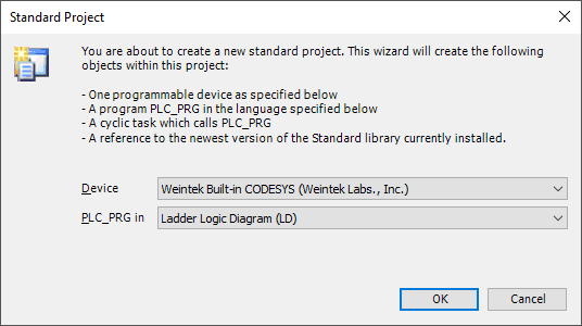
Step 2: Open the Codesys IDE and create a new “Standard project” or open an existing project.

Step 3: When prompted, ensure that “Weintek Built-in CODESYS” is selected.
Step 4: Within the project tree, double click “Device (Weintek Built-in CODESYS)”.

Step 5: Select the “Gateway” and click “Add Device…”.
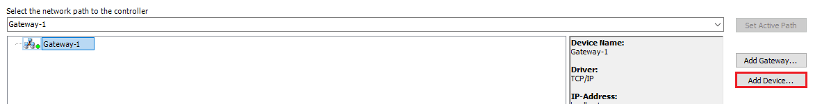
Note: If the “Device” tab appears as depicted below, please enter the HMI’s LAN-2 IP into the entry box on the far right and click the [Enter] key. When finished, proceed to step 8.

Step 6: Within the following menu, enter the IP address of the HMI’s LAN-2 port.

Step 7: The HMI will append to the Gateway instance. While the HMI is selected, click on the “Set Active Path…” button.

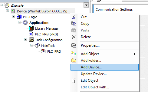
Step 8: Within the project tree, right-click “Device (Weintek Built-in CODESYS)” and select “Add Device…”.
Step 9: Within the following menu, select an “Ethernet” adapter with version 3.5.15.0 and click the “Add Device…” button in the bottom right corner.
Note: This driver should be appended to Weintek’s Codesys package, however, you may need to select the “Display all versions” check box to view this driver.

Step 10: With the “Add Device…” menu still open, click on the “Ethernet” driver within the project tree and select an instance of a “Modbus TCP Master” with version 3.5.15.0 and click the “Add Device…” button in the bottom right corner.
Note: This driver should be appended to Weintek’s Codesys package, however, you may need to select the “Display all versions” check box to view this driver.

Step 11: With the “Add Device…” menu still open, click on the “Modbus_TCP_Master” driver within the project tree and select an instance of a “Modbus TCP Slave” with version 3.5.15.0 and click the “Add Device…” button in the bottom right corner.
Step 12: Double-click on the “Ethernet” device within the project tree and click on the ellipses within the following menu.

Step 13: Within the “Network Adapters” menu, please select eth0 and click “OK”.
Note: [Optional] Double-click on the “Modbus TCP Master” device within the project tree and ensure that “Auto-reconnect” is selected.

Step 14: Double-click on the “Modbus TCP Slave” device within the project tree and configure the IP address within the “General” tab. To map a variable to a Modbus address, you must configure each target address within the “Modbus Slave Channel” tab. To add a channel, select this tab and click on the “Add Channel…” button.
Note: By default the unit ID of the Modbus TCP slave is set to 255. If the device that you are attempting to write to utilizes a different unit ID, please use Modbus TCP Slave version 3.5.10.0.

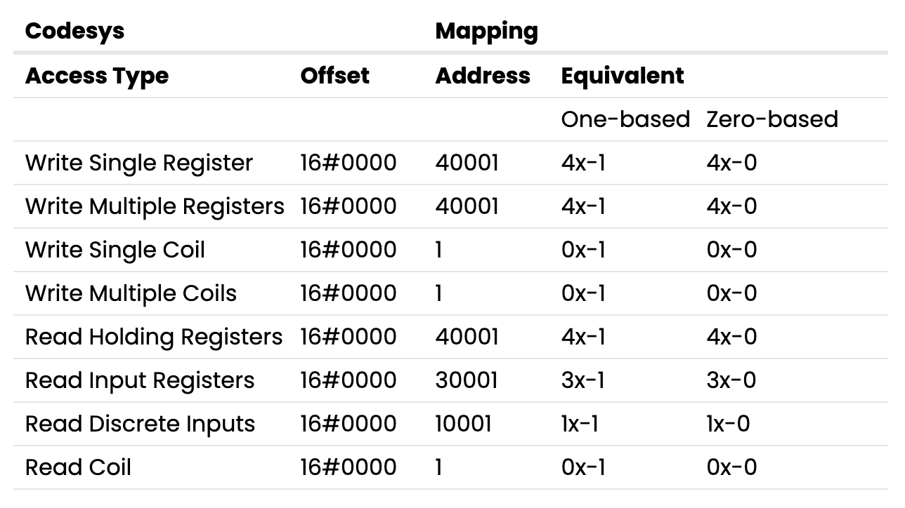
Step 15: The Modbus addressing depends on the specifications of the target device and vendors may choose to display addresses as shown within the “Address” or “Equivalent” column.
Note: Some vendors may choose a one-based representation, in such cases an offset of 16#0000 with “Write Single Register” selected will map to register 4x-1 or 40001 within the target device.
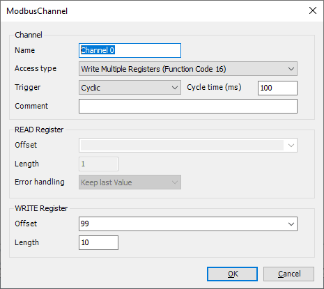
Step 16: Configure the channel such that it maps to the desired Modbus register.
Note: Channel 0 will allow us to write to 4x-100 ~ 4x-109 (One-based). Channel 1 will allow us to read from 4x-5~ 4x-9 (One-based).
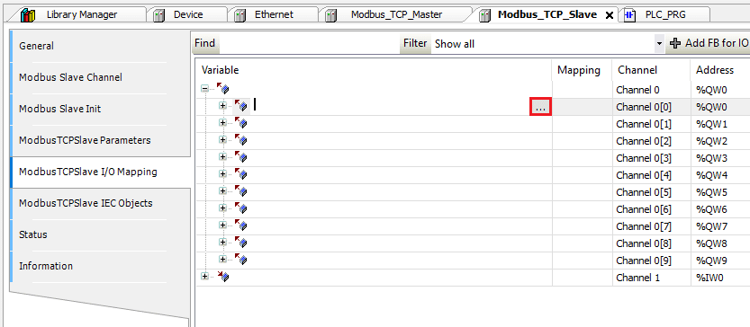
Step 17: To map a variable to a Modbus address select the “ModbusTCPSlave I/O Mapping” tab. To map a variable to an I/O point, declare the variable within a POU, GVL, or PVL.

Step 18: Once a variable has been declared, select the “ModbusTCPSlave I/O Mapping” tab within the Modbus TCP Slave device and double-click next to the desired I/O point in the “Variable” column. When prompted, click on the ellipses.
Step 19: Ensure that the desired project variable is selected and click “OK” to map this variable to the I/O point:
Note: If the variable mapped to an IO point is not used within the ladder, the data within the IO point will not be polled by the PLC.

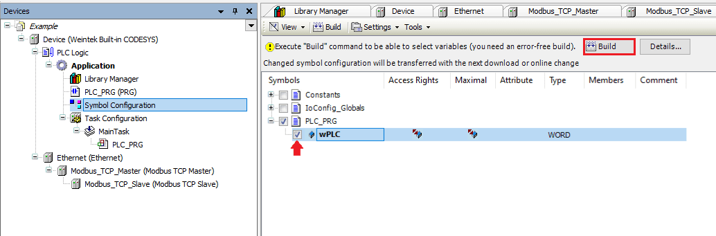
Step 20: When the project is finished, right-click on “Application” and within the “Add Object” list click “Symbol Configuration…”. When prompted, click “Add”.

Step 21: Select “Build” within the following menu to verify that the application is error-free. Ensure that each tag that you wish to export is selected within this list.
Step 22: Within the “Build” tab, click on “Generate code” and an .xml file called “[PROJECT NAME].Device.Application.xml” will be saved within the same folder as the project file. We will use this file to import tags into EasyBuilder Pro.
Note: New tags that do not automatically import into EasyBuilder Pro. If you create a new tag within your Codesys project and wish to access it from EasyBuilder Pro, ensure that each tag you wish to export is selected before selecting “Generate Code”. Then, import the .xml file into EasyBuilder Pro.

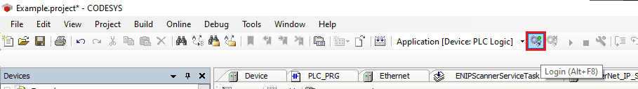
Step 23: Before you save and exit the application, please click the “Login” button to download this project to the HMI. If prompted to “proceed with download” click “Yes”.
Note: Subsequent changes may display the following menu. If prompted, ensure that “Login with download” and “Update bootproject” are enabled.
Step 24: Click the “Start” button to place the Codesys application in “RUN” mode.

EasyBuilder Pro
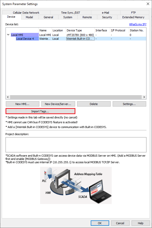
Step 25: Open an instance of EasyBuilder Pro and select the HMI that you will use within this application. Once open, select the “New Device/Server” button within the “System Parameters”.

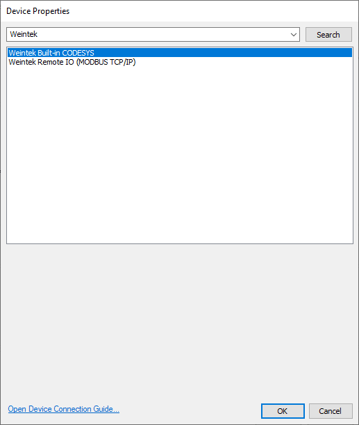
Step 26: Within the following menu, click on the center of the “Device type” drop-down list.

Step 27: A popup dialog will appear, within this dialog please search for and select the “Weintek Built-in CODESYS” driver and then click “OK”. Configure any additional settings and then click “OK” once more.
Step 28: While the “Weintek Built-in CODESYS” driver is selected click on the “Import Tags…” button.
Step 29: Within the following menu, select either “One char per word” or “Two char per word” depending on your preference of STRING representation, and click “OK”. Locate the .xml tag file titled “[PROJECT NAME].Device.Application.xml” and click “Open”. A popup will appear that says “Imported tag information successfully.” Click “OK”.

Step 30: It is now possible to reference objects by selecting a tag within an object that corresponds with its data type.
Note: Within EasyBuilder Pro tags can be viewed and selected within an object. There is no utility that allows you to view all tags simultaneously.
For more detailed instructions, please refer to the Weintek Forum !
Best Practices for Integration using Modbus TCP
When working with Modbus, it’s essential to pay close attention to vendor-specific address offsets. Modbus uses absolute addressing, where memory is organized in either 16-bit or 1-bit arrays. The starting element may be 0 or 1, depending on the vendor. For example, 16-bit “holding” register addresses in documentation often begin at 40001 or 40000.
CODESYS, however, uses a 0-based offset. This means that reading from address ‘0’ could correspond to either 40000 or 40001, depending on the vendor’s definition of the first address. Always consult the device manual to verify the correct address mapping and offset.
It’s also critical to understand which function codes (sometimes abbreviated as FC) are supported by the device. Modbus function codes define the type of command being sent—for instance, function code 3 (0x03) reads holding registers. Using unsupported function codes can lead to communication errors, abnormal behavior, or frequent disconnects.
Key Takeaways:
Share this article
Facebook Instagram Linkedin Twitter Product HMI / PLC IIoT / VPN Company About Contact Us Resources Forum YouTube Terms of Service Privacy Policy © 2025 Weintek USA. All rights reserved.
Source: www.weintekusa.com
Open the booklet / download PDF